Vendetta V20 Build diary 2016

ratz

Wielder of the Rubber Mallet
At this point we are going to set aside the A67 seven wheel and use the Reynolds Brand wheels for this particular build. This set will be an 45mm carbon Reynolds "Assault" drive-wheel and a 60mm "Strike" rear wheel. This combination can be purchased from wheelbuilder.com if you provide them the specs you need. The mixed depth combos are becoming really popular, but of course the stock ones are backwards for a FWD bike so you need have them custom built.

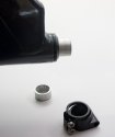
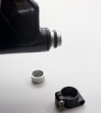
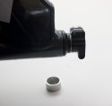
For this build we are using SRAM XG-1190 X-Dome cassette. This thing is a beauty and deserves a close up look. The cassette is almost all one piece.

Cool Cassette - 2 of 3.jpg

With elastomer between each cog to dampen vibrations and noise.

Cool Cassette - 3 of 3.jpg

The cassette installed with the standard SRAM cog and lock rim.

Cool Cassette - 1 of 3.jpg

Installing the cassette is trivial as always.

Install Cassette - 1 of 5.jpg

Slide on to free hub.

Install Cassette - 2 of 5.jpg

Grease the lock ring thread.

Install Cassette - 3 of 5.jpg

Grab a cassette socket.

Install Cassette - 4 of 5.jpg

Torque the cassette down to 40nm

Install Cassette - 5 of 5.jpg


The best part about installing a cassette is you don't need a chain whip to do the install :cool:
 

ratz

Wielder of the Rubber Mallet
Put the rear wheel into frame and fasten the quick-release and spin it really really fast... (you know you want to)

Install Wheels - 1 of 5.jpg

Install the front wheel, and verify that the cassette clears the fork.

Install Wheels - 2 of 5.jpg

Check the front tire clearance

Install Wheels - 3 of 5.jpg

These are 23c tires, 25c will fit fine; 28c is going to get tight depending on the rim and tire combination choice.

Install Wheels - 4 of 5.jpg

Install Wheels - 5 of 5.jpg
 

ratz

Wielder of the Rubber Mallet
Install the handle bars into the clamps at the end of the slider.

Install Handlebars - 1 of 2.jpg

Only snug the bolts. We now have an assembled frame that is ready for the drive train installation. We'll come back to handlebars after the bike is fully assembled to compare several different options for the bars.

Install Handlebars - 2 of 2.jpg
 

ratz

Wielder of the Rubber Mallet
Now that the frame is together; it's time to get the seat ready for install on the bike.

One of the nicer touches with the new include parts is the inclusion of the correct bolts and nuts for installing two water bottle under the seat. For this build we are going to install our Aero bottles under the seats. These bottles use carbon cages so we'll be added wasters to improve the fit. We start out with the two bolts and the two nuts provided. We add in two larger washer and two smaller washer. And we install these with a torque wrench.

The large washers go against the bottom of the seat.

DSC05942.jpg

The bottle cage sits on top of the big waster; and the the small washer go on the bottle cage.

DSC05944.jpg

Slide the bolts from below and install the nuts. Torque to 4nm.

DSC05945.jpg

In the case of our seats are going to add two additional holes. Using a high speed drill; we drill from the back to the front. Use a new drill bit and you'll get a perfectly clean hole in the carbon fiber seat. (These holes were aligned on the bike). Using the holes we are mount the bracket to hold our Upstand brand kick stand.

DSC05946.jpg

Once done we can install the seat on the bike and finally sit on it.
 

ratz

Wielder of the Rubber Mallet
Installing the cranks is a pretty straight forward step that I normally don't document. But This time we are adding Rotor Cranks. These use the 24mm straight through Shimano like system. Since these are a little tricky to install on a Vendetta we'll document it this time around.

We are using angular bearing in our bottom bracket so we have to add wave washer and a plastic spacer. grease those and slide onto the crank arm.

DSC05911.jpg

Slide the crank into the Bottom Bracket and install the O-ring on the non-drive side

DSC05928.jpg

Use the bolt on the crank arm to open the arm clamp. This bolt gives; a clamp position, a neutral position and a pried open position. In the neutral position the crank arm will not slide on; you must use the bolt to pried it open enough to slide it on.

DSC05929.jpg

Slide the crank on; then tight the bolt only enough to get to the neutral position

DSC05930.jpg

Install the end cap. This will just barely thread in. You aren't tightening it; you are just installing it and starting the threads so that it stays in place.

DSC05931.jpg

Spin the cranks they should spin really freely and go and go and go.

Using a 7nm torque wrench tighten down the crank arm.

DSC05935.jpg
DSC05936.jpg


Using a 6nm torque wrench tighten down the end cap.

DSC05937.jpg
DSC05938.jpg

After words the crank arms should still spin just its freely as when you started. If not, you have over tightened the cranks latterly. If there is left right play; then they are too loose. These are very easy to install once you get use to the process; but when you do it the first time you'll be convinced everything is too loose. Just keep going and trust the system.

DSC05880.jpg
 
Last edited:

ratz

Wielder of the Rubber Mallet
Ok now to back up and cover another topic specific to smaller riders. Those riders that are smaller of stature or lacking an aero belling might find the default boom configuration to be too high. When that is the case you can cut your fork stem to lower the boom and handle bars. The stock fork is sized for the middle ground. Extremely large riders may need a stem extender and short riders might choose to cut the stem.

For certain, this stem cutting is not something you can really tell until you get the bike to the stage we are at now and you can sit on it. Riders experienced with the Cruzbike platform (especially riders of previous version of the Vendetta and to some extend Silvio riders) will likely know right away if they want to make this modification after sitting on the bike. Others will need to ride the bike many miles before they decide this is for them. Don't perform this modification until you are sure.

So with that said, Mrs. Ratz need a lower boom so we are cutting her stem.

The first step is to drive the star nut far enough into the stem so that you can cut. In our case we are going to replace the two large spacer with 1 thin one. Using the spacer themselves, we measure the difference in them and the we screw the bolt into the star nut so that it sticks out just that measure distance from the top of the stem. Then using a trusty rubber mallet we gently pound that bolt into the stem so that it is flush with the end of the stem. This moves the start nut a distance equal to the amount we are going to cut off. Take you time and be gentle.

DSC05918.jpg

With star nut in the correct position we score the outside of the stem at the distance that we want to cut. Then attached the fork to something stable to make the first cut with our pipe cutter.

DSC05919.jpg

Then we cut the end. Yes it's ok to freak out the entire time you do this, but it's a fairly come bike building step when fitting forks to custom frame. After the cut clean up the burs on the end of the metal.

DSC05921.jpg

Put the fork back into the frame as discussed earlier and install the dust cover

DSC05922.jpg

Install the small spacer

DSC05923.jpg

Reinstall the pivot clamp

DSC05924.jpg

Install the stem cap

DSC05926.jpg

and now we have a bike with a lower boom for a smaller rider

DSC05949.jpg
 

ratz

Wielder of the Rubber Mallet
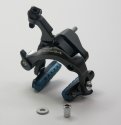
For this build we are using a TriRig Omega X front brake. The aero benefits of this brake most likely don't matter on the Vendetta since it's down in the leg wash. However it's a really cool looking brake, and it has less left and right size than a standard caliper brake; and it's center pull design ensures that the brake cable will never be in a place that your leg can strike it.

DSC05882.jpg

Due to the fork design of the Vendetta and Silvio we will need the Long install bolt included with the brake. We'll also need to use the Big and medium offset washers included with the brake. TriRig brakes go on many exotic bikes so the bolts provided can handle the long offset versus the fork.

IMG_5024.jpg

Unfortunately the 15mm mounting nut included is too short it will work but it doesn't give much engagement. So a 30mm is recommended. Cruzbike use to include those but this kit didn't' come with any, but these are really cheap and can be gotten from numerous supplies for $5-10.

IMG_5029.jpg

In these pictures too many spacers are installed the final build has a really nice 1.5 mm gap between the brake and fork. (Oddly like all of our Silvio and Vendetta forks; there is less clearance on the left hand side fork arm than there is on the right side, where the brake sits in front of the fork)

IMG_5027.jpg

IMG_5032.jpg

These brakes will fit on the rear position as well; it's a tight fit on the top mounting position; and an easy fit on the lower position. However I don't recommend running it as a rear break. The spring bar on these brakes is not enclosed and it's removable. The brake was never envisioned to be running in a horizontal position; after looking at it at length, it seems pretty certain that the spring bar could vibrate loose and fall off if run in a horizontal position.

DSC05886.jpg

So for the rear brake we are using the tried and true Ultegra 6700 caliper brake. This brake will fit and work in both the lower and the upper position. In the upper one it's a snug fit and you'll need a cable frame rub protect but it's worth the hassle to get the brake install in that position and leave your lower triangle free for cargo when needed.

DSC05961.jpg
IMG_5055.jpg
IMG_5053.jpg
 
Last edited:

ratz

Wielder of the Rubber Mallet
At this point in the diary we are going to have to take a break. Next up is installing the SRAM RED E-tap wireless derailleur system. These are new this year and currently on back-order. We have the order in and our spot in the queue. Now we are waiting for them to ship. Estimates place that between the middle of February to the end of April. As soon as they are in the house we'll resume the build. If things really drag out we'll get some cheap brifters and at least conduct the handle bar testing. Already shown so far have been the Midge On-One bars and the Salsa Cowbell bars and we have a couple of others to compliment those.
 

ratz

Wielder of the Rubber Mallet
Well sad to report that our order for SRAM E-Tap was cancelled by the supplier because SRAM pushed out the shipping date. As such we lost our spot in the queue. So while I search for another source I thought we would do an update with some parts we do have.

So today we are going to make Frogs Float.

When picking a Clipless pedal for your Vendetta it's important to pick a pedal that matches your body needs and your goals. For a lot of people (not everyone) these goals include

Easy Clip in
Easy Clip out
A walkable Shoe
Certainty of unclipping when falling
Lots of "float" to protect the knees
Affordable

Ticking all those boxes is the venerable "Frog" pedals from Speedplay. The Cromoly version of these can be had for around $105US and the Stainless ones for $135. You really should not use the Titanium ones on a Recumbent bike because they have a weight limit and you could easily exceed that amount of force if you brace into the seat and push hard.

The Cromoly option, has a black painted spindle that might chip over the course of time and you should be prepared to touch them up with paint to prevent rust; otherwise they are functionally equivalent to the Stainless option and about a 5g delta in weight.

DSC05968.jpg
Frogs have been around a long time. They are a mountain bike pedal with a 2 hole cleat. As such they work with all walkable MTB two hole shoes.

The cleat and pedal are completely spring-less; making them pretty much the easiest pedal on the mark to "click into". With the frogs you simple place your foot up by the pedal and click you are attached. If you have ridden other clip-less pedals it is rather shocking how easy it is. This is my personal favorite pedal for teaching people to ride clip-less on.

To unclip from Frogs you simply rotate your heel out past 15 degree and the shoe literally falls off the pedals. Oddly this disengagement is not something that happens accidentally; they float so freely that at time you will think that would happen, but in practice it just does not happen.

As designed the Frog pedal only disengages with a heel "out" rotation; there is a physical stop on them that lets you squeeze your heels inward that ensures you stay locked in. This feature was meant to allow MTB riders to got air born while squeezing there heels to ensure the bike stays attached to the feet. The rotation stop also ensures you heel does not come into contact with the crank arms or the chain stay. These are both good design elements and they can be used as is with a Cruzbike or other recumbent. However, for riders with bad knees that lack of inward float of about 1-5 degree can be frustrating and can aggravate finicky knees. If you are a rider with knees that need more float you are in luck because the frogs can be modified to be the best free floating casual pedal available. So lets take a look at this modification. If you don't like the modification it's trivial to undo it.

To setup the Floating frogs and shoes you need; Pedals, a Grease gun, a thin knife, and a 2.5nm torque wrench. You might be thinking, I'd don't want to buy a Pedal grease gun, but really if you do not have one your pedals are probably letting you down as most pedal designs should be greased at least once a season probably twice; and it really is trivially cheap and easy to do.

DSC05969.jpg

Using 4mm allen remove the two screws from the left and right of the pedal body.

DSC05970.jpg

Insert a thing knife into the tiny notch on the back edge of the pedal. The bodies are designed to come apart for maintenance and replacement. Look closely and you will see the notch for separating the halves.

DSC05971.jpg

Pry the body apart.

DSC05972.jpg
Remove the spindle. This might be a touch hard; the factory pedals have some glue to hold the halves together and some always seems to get on the spindle making it hard to remove. There are no plastic pieces holding it in place; just give it a firm tug and it will come out; there is nothing to break.

DSC05974.jpg

Repeat the process with the second pedal. Then with both pedals apart; simply SWAP the spindle. Pair the Left spindle with the right pedal, and the right spindle with the left body; and reassemble. You now have two pedals with full float.

The last step for the pedals is to re-grease them. Remove the screw from the end of the pedal.

DSC05975.jpg

Insert grease gun

DSC05976.jpg
Squeeze in grease until some comes out the spindle side of the pedal.

DSC05977.jpg

Comparing a modified and unmodified pedal you can see that the rotation stop is now at the front of the pedal and will never actually engage with the cleat, thus giving you a full float pedal.

DSC05978.jpg
 

ratz

Wielder of the Rubber Mallet
Installing the cleat on to the shoe is simple, but futzy. The cleat is in three pieces: the cleat, the lock pad and the lock lifter. On the end of the cleat you will see an adjustment screw. Do not mess with that screw, it is factor set and frozen in place with red lock-tite. If you ever need to adjust that screw in the future due to cleat wear; you will need to heat the bolt with a soldering-iron to break the lock-tite loose. If you fail to do that you will just break your allen wrench attempting to turn the bolt.

Insert the lock pad into the cleat,

DSC05981.jpg

then put the lifter over the plate

DSC05982.jpg

Lastly the futzy part; hold the three pieces in your hand; flip them over and press them against the shoe. They will likely fall apart in your hand 7 or 8 times before you get them mounted.

I find it easiest to get them against the shoe by the arch and then slide the assembly forward and into place. Add blue lock-tite to the cleat screws and tighten down with the 2.5nm torque wrench in the most rearward position possible.

DSC05983.jpg

Always use the screws that came with the cleat not the ones with the shoes which are likely for SPD cleats and far too long. Also for any shoe do yourself a favor and get a 2.5nm torque wrench; that $9 tool will ensure you do not ruin your $150-200 shoes.

Now with it is time to go on an E-Tap hunt and in the meantime see if I can figure out a way to do the handle-bar testing without a drive train installed. Stay tuned you might just be witness to the first "fixie-V20"
 

ratz

Wielder of the Rubber Mallet
So at this point I could probably start a new thread call Seeing RED for a number of reasons. Nevertheless, a long last it is time to get our E-TAP install under way.

In case you are not the a big bike and gadget nerd, E-Tap is Sram’s entry in the electronic shifting game. What makes E-tap exciting is that it is a wireless shifting setup. This removes the routing of cables, hiding of batteries, and the constant tuning of derailleurs due to cable stretch.

Back when I did the Di2 builds of our Silvio and Vendetta; I spent around 14 hours planning, measuring, ordering, testing and drilling holes for the wiring and the battery. In the end, the results were great but, I was left with a clear idea that any other builds I did like that would take 1-3 hours of extra work to do it right. So when SRAM announced E-tap I was all in, even if I had to work with round 1 of the product which was bound to be risky being a Gen 1 product.

So orders were places in November and with some luck we managed to get 2 of the first group sets shipped to our area that were not mounted on a completed bike. The box itself arrived after a painfully slow shipping process; apparently the high capacity batteries SRAM selected can not be shipped by Air due to restrictions on L-ion batteries shipping. When you finally see the batteries, this can only make you laugh, as they are the size of a large thumb.

So the box arrived; all 15 lbs of it (times 2).
DSC05984.jpg

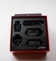
Opening the magnetically sealed lid reveals 6 largish boxing holding each of the components.
DSC05985.jpg

Beneath the boxes are the cabling and housings that complete the group-set.

DSC05986.jpg

The boxes clearly designed for down-stream use when selling individual pieces.

DSC05990.jpg
DSC05993.jpg

However, one has to question the use of an entire box to hold the firmware upgrade stick

DSC05992.jpg


The front and rear derailleurs each come with 1 battery and covers so that you can protect the electronic if transporting the bike long distances on a rack. The battery covers also have a small tab on them so that you can mark which batteries are charged and which ones are spent. Very handy little inclusion for our multi-day event riders. Batteries themselves came slightly charged. Battery life is rate at 1000 kilometers per charge and a 200 charge life cycle before they have to be replaced.

DSC05995.jpg
DSC05996.jpg
DSC05997.jpg
DSC05998.jpg
 

ratz

Wielder of the Rubber Mallet
The brifters are very much like all standard SRAM brifters; with two notable exceptions. First, the long throw mechanical levers have been replaced with large plastic buttons. The other change is that the obnoxious wide flare of the brake levers has been reduced to something tolerable and less likely to cause cosmetic damage when leaning the bike against a wall.

DSC05999.jpg

The brake levers themselves are carbon; but if you didn’t know they were carbon you’d swear they were made out of some space age plastic. They have none of that hi-gross hard and strong feel most of us associate with bike carbon. So far I’m not a big fan of how the feel in my hands, they just feel cheap and don’t inspire the confidence I want from my brake lever. Time will tell if I get use to them after they are wired up on the bike and pulling cable.

The charger did come with international adapters including plug adapters for US Std, Uk Std, and Continental Std. That was a nice touch.

DSC06000.jpg


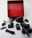
When it’s all unboxed you have this

DSC06002.jpg


Which takes up this much space

DSC06005.jpg

And you are left with this to deal with from just two bikes

IMG_5095.jpg

Now I am not one to run around and yelling Live Green, Live Green, but even to my generally middle of the road opinions on such things I must say that I find this packaging to be a joke.

Whoever at SRAM designed this packaging was clearly over-focused on making the customer feel like they really got there money’s worth but they completely missed that in today’s world we can do a lot better. Hopefully as they invest the profits in Gen2 and the Force versions of E-tap they will go back and design some more responsible packing. Consider for a minute that 90% of these boxes will wind up in the bike shop dumpster and the customer will never see any of it; that leaves me scratching my head.
 

ratz

Wielder of the Rubber Mallet
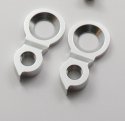
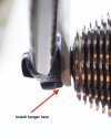
Mounting the Rear Derailleur was completely straight forward. First the derailleur hanger has to be installed. I left this step until now as it made the frame easier to work with and set on the ground without the hanger protruding. Simply unbolt the wheel; spread the fork and change stay apart and the axel and slide one of the two provide handers into place. Bevel edge facing outwards. Slip everything back to together and tighten the wheel. The part is press fit and the press from the wheel will make the mounting semi permanent. When changing the wheel the hanger will stay in place and hold the derailleur. In the event of a crash where the derailleur is impacted, the hanger will break to protect the frame form damage and can then be removed and replaced with a new one.

Version 2.jpg Version 2 (1).jpg
So bolt the RD on to the Hanger and torque to 6.0nm.

DSC06012.jpg DSC06013.jpg
Use the button on the derailleur to move it the most inboard position. Single tap the button to move out; double tap to move in. The double tapping part is tricky at first.

DSC06014.jpg
Adjust the lower limit screw to line up the pulley with the biggest sprocket on the cassette. In this case, the 28T
DSC06019.jpg

Lastly adjust he b-screw so that the pulley is positioned with 6mm gap between it and the cassette when in the running position; measure with #6 Hex wrench.

DSC06019.jpgDSC06017.jpg
Shift the derailleur to the most outboard position and use the high limit screw to align the pulley with the 11T sprocket.
 

ratz

Wielder of the Rubber Mallet
Where Rear derailleurs and me always get along. Front Derailleurs and me have a love hate hate relationship. I love a good working front derailleur; but I hate installing them and I hate tuning them. Perfectionists and Front Derailleur are a challenging combination.

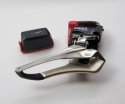
The SRAM e-Tap is a Yaw derailleur. Simply put, Yaw is SRAM solution to allow people to cross chain their drive train. Making that possible allows SRAM marketing can tout the fact that you are buying a 22 gear product and all gears are useable. Not that any of us would actually cross chain when riding our bikes. But should we need to do it SRAM Yaw will let you do it all day without the sound of chain rubbing on your cage and making noise to alert you that you are dong something dumb. The skeptic in the audience might think that is a great way to make sure people have to replace their cassette, chain, and chain rings more often.

A Yaw derailleur accomplishes it magic by have the front of the cage move less than back of the cage. It basically pivots along the chain line as it moves in and out.

Because of Yaw, SRAM elected not to build auto trim into the front derailleur. Shimano Di2 employs auto trim to accomplish the same thing. With auto trim, the front derailleur is aware of the position of the rear derailleur and can make micro adjustment in position (after the chain stabilizes) to all more room for cross chaining. SRAM could well have done this, but it puts a serious demand on the battery to power all the extra micro shifts. So in the end SRAM stayed with Yaw which when setup works well. On a normal bike most people would never notice the difference; but Yaw can pose some extra challenges if you start mixing and matching component families. As I was about to learn the hard way.


To install the Front Derailleur screw in onto the stem and make it snug so it can just barely move; don’t torque at this time.

DSC06020.jpg
A YAW derailleur requires you to perform two alignments. Move the derailleur to the outboard position using the button on the body.

Align it over the larger chain ring. Position vertically so that the top of the teeth line up with the mark on the inside of the derailleur. The teeth must pass though that etched area to prevent over shifting.

In the case of our build we are using Q-Ring. With Q-ring you align the tallest tooth. On current Q-rings that tooth in the one above the “TW” in the printed patent statement on the ring.

DSC06021.jpg

Again gently tighten the screw to keep the unit is place.

The second adjustment is the pivot of the derailleur. On the top of the derailleur there are to mark that need to be centered on the chain line as it runs from the Big Chain ring to the smallest sprocket.

IMG_5085.jpg

Now all projects run into unexpected snags and this is where we hit ours.


The Rotor 3D cranks we where using don’t work with the YAW derailleur. These particular cranks have a Chain ring spider that places the Rings 5mm further outboard from the Bottom Bracket than a SRAM crank sets. 2.5mm that spacing comes from moving the chain ring closer to the crank arm and the other 2.5mm is in Q-factor.

This has always worked fine on the Silvio and Vendetta with the Di2 setups (with the Vendetta needing a 1mm space on each side of the bottom bracket cups to clear the chain stay clamps). I have always liked the 3D cranks they are super light and scary stiff; perfect on the nose of a Vendetta.

But, when it came time to line up the pivot on the YAW derailleur. There was not enough room and the crank arm would hit the derailleur cage. After much fusing, cussing and tweaking the best we could get was a 1mm clearance and that’s just too close for comfort and shifting was still sub optimal.
IMG_5086.jpg IMG_5087.jpg IMG_5090.jpg
 

RojoRacing

Donut Powered Wise-guy
Question
Do you have access to a Red22 rear derailleur? While out on the mtb today I had the idea that if the etap is basically 22 of electric steriods the it could be possible to swap the a med length cage from a 22 onto an etap and gain the use of a 32t cog. What are you thoughts on that idea?
 

ratz

Wielder of the Rubber Mallet
So we have to stop our build and blow things up.

First we are going to need a new and different crankset and power meters.

Second to make things more fun. During all the futzing we discover that the lower limit screw on one of the front derailleurs had too much blue Loctite on it from the factory after only 3 or 4 adjustment one of our lower limit screws jammed and the head stripped out.

SRAM stepped up to the plate on the stripped screw. I explained to them that it stripped under normal and expected adjustments. They replaced it out of Chicago in just 3 days after the 2 days of preliminary phone calls to figure out I had to take it to a local bike shop instead of working with the online supplier. Surprise surprise they shipped the replacement by air; but but but what about the batteries? I'm so confused now.

The cranks on the other hand were a little more involved.

Last year I determined that with both the riders in our household at sub 5’10” but with long legs; it appears 155mm cranks would be more optimal than our 165mm. At one time I had a test set of 150mm ones, but that was a tad too short or too much of a change from what we where use to. At that time we also wanted power meters on the bikes for formal and structured training. To get to 155 cranks would mean; getting Garmin Vector pedals and giving up our Q-rings.

Q-rings are “purple” I don’t know if they really work. But my knees hurt less pushing them versus round rings. I also know a lot of smart people that understand that stuff better than me that can give you their reasons for why q-rings are better. But we are not here to review or debate that it's just my bias for this build.

So The idea of loosing the q-rings and getting vector pedal that are finicky about torque and proper setup; wasn’t appealing. We elected to do nothing on the crank lenght front until things evolved more (there were a lot of new products coming.) So we stayed with 165mm cranks and power2max meters which were the shortest and most reliable hassle free meters that were compatible with the Vendetta TT and Silvo 2.

Fast forward to this build and to save time and money we moved the Power2Max Rotors over. So much for saving time and protecting the budget.

So today we now have on the market the PowerTap P1 pedals which have three things I really like: they run on AAA batteries, The don’t require torqueing on the cranks; and they support Q-rings by taking 40 angular momentum measurements per rotation (Not as good as Power2max’s 60 but good enough).

Before preceding with any other ideas on this project refactoring, I grabbed an old set of SRAM Rival cranks and verified that the ETap derailler worked with SRAM’s legacy cranks. I just needed to verify that I was not going to need one of the new 22 series to get this to work. Thankfully, my 5-year-old rivals fit just fine with the derailleur.
 

ratz

Wielder of the Rubber Mallet
So it was time to make the switch to 155mm cranks. This was no small switch over. We have 4 bikes with 2 on trainers and 2 on the road, and you can’t really train on different crank geometries. So this YAW problem had a really large impact. (You want to run the new-stuff? Want your spouse to like the same sports be careful what you ask for.)

We contacted Mark at bikedesignsmith.com ordered up some 155mm SRAM Apex cranks. Sure I could have probably done it cheaper just buying them and having a machine shop tap them. But 155mm require the hard to fine 180mm cranks and really at this point Mark knows what he’s doing and made use 4 sets in 3 days. I've had my fill of surprises and I don't mind supporting Mark since a main reason we can get short cranks is based on his involvement with the MN bikes scene for the last 40 years. That and it's fun to visit his basement shop.

While I was waiting on the cranks there were a couple of other loose ends to tackle.

First our Bottom Brackets are Enduro XD-15 configured as 24x24 for the 3D cranks and the Apex is a GXP 24x22 Bottom bracket. Fortunately nothing to buy this time. Our Enduro’s use to be 24x22 and I had hammered out the 2mm space from them when I converted to Rotor. Being unable to throw away old parts because you always need what you threw away last month; I still had the spacers and was able to pound them back into the BB and test fit some GXP cranks to make sure it would work. Phew that means no new expensive Bottom Brackets.

IMG_5084.jpg

The second item on the yet to be figured out was the capacity of the derailleurs. The ETap has a 31 Tooth capacity FDBig-FDlitte + RDBig-RDLittle <= 31. And we have 52-36+28-11=33 Oops !!!

The idea of going to 50 big ring and loosing speed; or a 38 and loosing climbing was not really appealing. I was going to try and just finesse it with the b-screw; but given the problems with the Cranks I decided not to push my luck. I rang up Rotor on the phone (yes phone not email) and found out that I could solve my problem using a QXL as my little ring. They actually consider the QXL little + Qring Big; an optimal setup and better that Q+Q on a compact. So we ordered up QXL 38T which have the same low end as the 36T Qring; and more power in the power stoke; but use enough chain to get us to the 31T capacity. The finished product does indeed shift better and I highly endorse upgrading your little ring to a QXL.

DSC06008.jpg


Ok so Cranks arrive. Pop the rings on; slide on the frame and torque down the GXP crank; and mount the derailleur and we are back to our point of failure. Yeah! (Power Meters still in route)
IMG_5093.jpg DSC06029.jpg


So at this point we line up the tallest tooth; and pivot the cage and tighten the derailleur down.

Pedal and test a few shifts. Yeah it shifts. At that point it is just a matter of setting the upper limit screw so there is 1mm of clearance; and the lower limit one with also 1mm of clearance. Test shift and all is good. When YAW works, it really is too easy. Even SRAM’s instructions over complicated it with an unneeded step 7 that is likely to make the installer screw up

It really is set vertical, Setup Pivot, set upper limit set lower limit. With electronic shifting, you are then done; as there is no wire to tension to dive the shifting.
DSC06034.jpg

DSC06042.jpg
DSC06037.jpg DSC06040.jpg DSC06044.jpg DSC06050.jpg

The bad part about YAW is if you have to redo it later; the derailleur comes from the factory with the limit screw “over” setup so that you can mount it fast and easy. To redo it you have to get the limit screws back into that default before you start; failure to do that and it’s really hard to install them. Check you tube for video on how to get it back to the default should you ever have to do a re-setup from scratch.
 
Top